 IMAGE Team - The Pantheon project
The Pandore implementation of the morphological operations depends on the image type.
Binary images: The value of a pixel is either 0 or 255 (which stand for background and object pixels). The set operations use logical operations such as AND, OR, and NOT.
Grayscale images: With pixel values not restricted to 0 and 255, the set operation uses ranking operations such MAX and MIN.
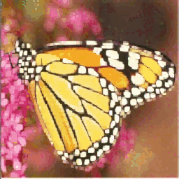
Color images: The color set operations consider the lexicographical ordering. The colors are ranked by using the red channel first, in case of equality of the red channel values then considering the green channel and finally the blue channel.
Multispectral images: This is an extension of color images, where the number of bands is not restricted to 3. However, multispectral set operations consider the marginal ordering, in which each band is processed separately.
Flat structuring elements are binary structuring elements considered as masks. Most of the time, the structuring elements are centered and are square matrices with an odd size: 3x3, 5x5, etc.
 |
 |
 |
| Diamond size 3. | Square size 3. | Disc size 3. |
 |
 |
 |
| Diamond size 7. | Square size 7. | Disc size 7. |
Most of the Pandore morphological operations use built-in flat structuring elements. Built-in structuring elements are centered and have an odd size: 3x3, 5x5, etc. Thus, the size parameter for the operator is actually the half-size (eg., 1 for 3x3, 3 for 7x7). In 2D, the predefined list of flat structuring elements is:
It is always possible to create a structuring element as a separate image that can be used with specialized Pandore operators. Any binary or grayscale image is convenient. Thus, custom structuring element can be built using arithmetic, logical, and morphological operations between basis structuring elements since they are implemented as regular images.
Building a structuring element image with a disc of size 7x7:
psedesign 2 3 se.pan
Building a structuring element image with a square of size 9x9:
psedesign 1 4 se.pan
Building a structuring element image with a diamond of size 3x3 from a text file:
cat > se.txt <<EOF
255 1 0
255 0 1
255 1 1
255 2 1
255 0 2
EOF
ptxt2pan 0 3 3 0 se.txt se.pan
Building a structuring element image with an empty square with a center:
pnewimage  7 7 0 0 tmp1.pan
psetborder 1 1 1 1 1 1 255 tmp1.pan tmp2.pan
pnewimage  7 7 0 255 tmp3.pan
psetborder 3 3 3 3 3 3 0 tmp3.pan tmp4.pan
por tmp2.pan tmp4.pan se.pan
pnewimage  7 7 0 255 tmp1.pan
psetborder 3 3 3 3 3 3 0 tmp1.pan tmp2.pan
pdilatation 0 2 tmp2.pan se.pan
The dilation of an image f by a structuring element B is the assignment to each pixel of the output image with the maximum value found over the neighborhood of the pixels where the neighborhood is defined by the structuring element B:
δB(f)x=max(β∈B)f(x+β)
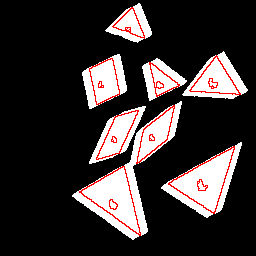
Considering binary image, dilation can be interpreted as the answer of the boolean question at each pixel: "Does the structuring element hits the pixel neighborhood?".
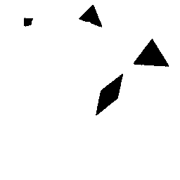
Dilation with a predefined structuring element (a diamond of size 7x7):
pdilatation 0 3 tangrambin.pan tangramdil.pan
Dilation with a customized structuring element (diamond of size 3x3 applied 3 times = a diamond of size 7x7):
cat > se.txt <<EOF
255 1 0
255 0 1
255 1 1
255 2 1
255 1 2
EOF
ptxt2pan 0 3 3 0 se.txt se.pan
psedilatation 3 se.pan images/tangrambin.pan tangramdil.pan
 |
 |
 |
| Black image with a white point. | Dilation by a square of size 7. | Dilation by a disc of size 7. |
 |
 |
 |
| Binary image. | Dilation by a square of size 9. | Dilation by a disc of size 9. |
 |
 |
 |
| Grayscale image. | Dilation by a square of size 9. | Dilation by a disc of size 9. |
 |
 |
 |
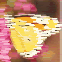
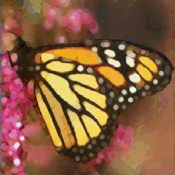
| Color image. | Dilation by a square of size 9. | Dilation by a disc of size 9. |
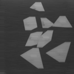
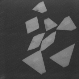
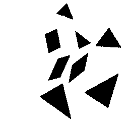
The erosion of an image f by a structuring element B is the assignment to each pixel of the output image with the minimum value found over the neighborhood of the pixel where the neighborhood is defined by the structuring element B:
εB(f)x=min(β∈B)f(x+β)Considering binary image, erosion can be interpreted as the answer of the boolean question at each pixel: "Does the structuring element fits the pixel neighborhood?"
Erosion with a predefined structuring element (a diamond of size 7x7):
perosion 2 3 tangrambin.pan tangramdil.pan
Erosion with a customized structuring element (a diamond of size 3x3 applied 3 times = a diamond of size 7x7):
cat > se.txt <<EOF
255 1 0
255 0 1
255 1 1
255 2 1
255 1 2
EOF
ptxt2pan 0 3 3 0 se.txt se.pan
pseerosion 3 se.pan images/tangrambin.pan tangramdil.pan
 |
 |
 |
| White image with a dark point. | Erosion by a square of size 7. | Erosion by a disc of size 7. |
|
 |
 |
| Binary image. | Erosion by a square of size 9. | Erosion by a disc of size 9. |
|
 |
 |
| Grayscale image. | Erosion by a square of size 9. | Erosion by a disc of size 9. |
|
 |
 |
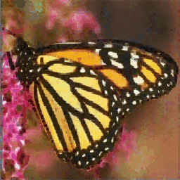
| Color image. | Erosion by a square of size 9. | Erosion by a disc of size 9. |
Linear dilation is a special case of dilation with a linear structuring element L. The operator pdilatation performs linear dilation with horizontal, vertical, and diagonal structuring elements. The operator plineardilation is more specialized for linear dilation and uses a parameter for specifying the angle rather than the structuring element.
Horizontal dilation with a predefined horizontal structuring element of size 7x7.
pdilatation 3 4 images/tangrambin.pan tangrambinld1.pan
Horizontal dilation with the angle=0° and the size 7x7.
plineardilatation 0 0 4 images/tangrambin.pan tangrambinld2.pan
Diagonal dilation with the angle=30° and the size 7x7.
plineardilatation 30 0 4 images/tangrambin.pan tangrambinld3.pan
|
 |
 |
| Dark image with a white point. | Horizontal dilation of size 7. | Diagonal dilation of size 7. |
|
 |
 |
| Binary image. | Horizontal dilation of size 7. | Dilation with angle=30° and size=7. |
|
 |
 |
| Grayscale image. | Horizontal dilation of size 4. | Dilation with angle=30° and size=4. |
|
 |
 |
| Color image. | Horizontal dilation of size 4. | Dilation with angle=30° and size=4. |
Linear erosion is a special case of erosion with a linear structuring element L. The operator perosion performs linear erosion with horizontal, vertical, and diagonal structuring elements. The operator plinearerosion is more specialized for linear erosion and uses a parameter for specifying the angle rather than the structuring element.
Horizontal erosion with a predefined horizontal structuring element of size 7x7.
perosion 3 4 images/tangrambin.pan tangrambinle1.pan
Horizontal erosion with the angle=0° and the size 7x7.
plinearerosion 0 0 4 images/tangrambin.pan tangrambinle2.pan
Diagonal erosion with the angle=30° and the size 7x7.
plinearerosion 30 0 4 images/tangrambin.pan tangrambinle3.pan
|
 |
 |
| White image with a dark point. | Horizontal erosion of size 7. | Diagonal erosion of size 7. |
|
 |
 |
| Binary image. | Horizontal erosion of size 7. | Erosion with angle=30° and size=7. |
|
 |
 |
| Grayscale image. | Horizontal erosion of size 4. | Erosion with angle=30° and size=4. |
|
 |
 |
| Color image. | Horizontal erosion of size 4. | Erosion with angle=30° and size=4. |
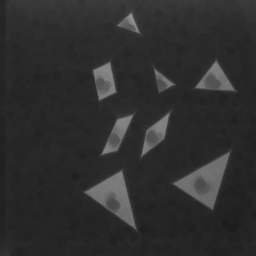
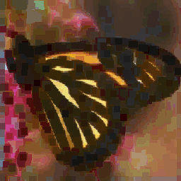
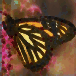
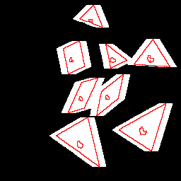
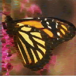
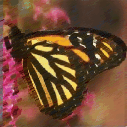
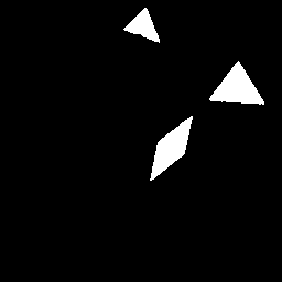
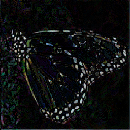
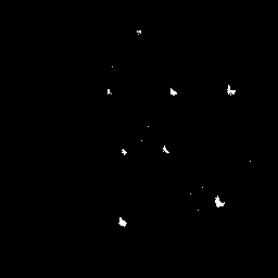
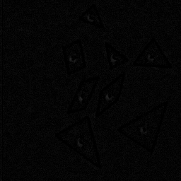
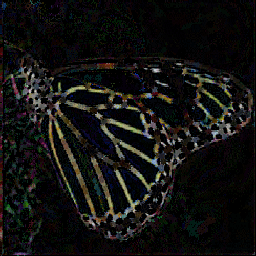
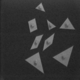
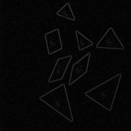
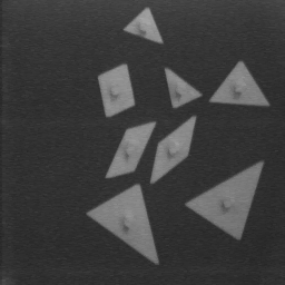
A geodesic dilation is a conditional dilation. An additional mask image g(x,y) is used as a limit to the propagation of the dilation.
δg(f(x,y)) = δ(f(x,y)) ∧ g(x,y)
The geodesic dilation used 3 parameters. The first two ones defines the structuring element, whereas the last one specifies the number of iterations.
Our implementation of the geodesic dilation also keeps the pixels of the source image that are masked by the mask image. Practically, we use:
δg(f(x,y)) = δ(f(x,y)) ∧ g(x,y) ∨ f(x,y)
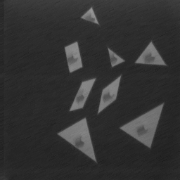
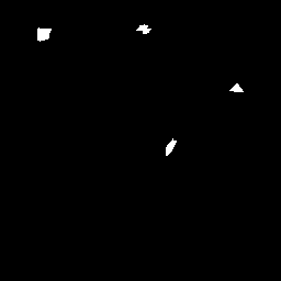
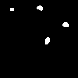
Geodesic dilation with a disc of size 1 applied 4 times.
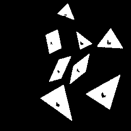
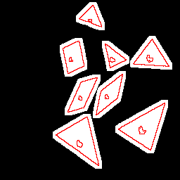
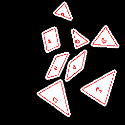
pgeodesicdilatation 2 1 4 tangrammarkers1.pan fillholbin.pan out.pan
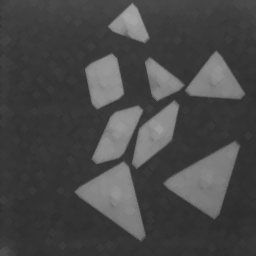
Geodesic dilation with a disc of size 1 applied 30 times.
pgeodesicdilatation 2 1 30 tangrammarkers1.pan fillholbin.pan out.pan
 |
 |
 |
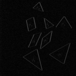
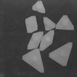
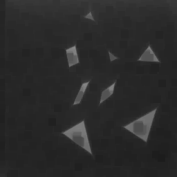
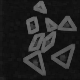
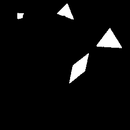 |
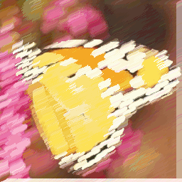
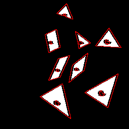
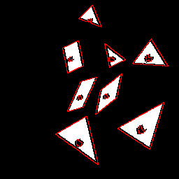
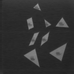
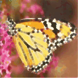
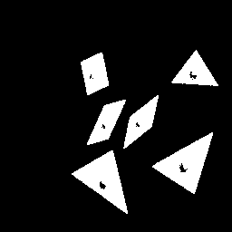
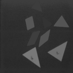
| Binary image. | Mask image. | Geodesic dilation by a disc applied 4 times. | Geodesic dilation by a disc applied 30 times. |
A geodesic erosion is a conditional erosion. An additional mask image g(x,y) is used as a limit to the propagation of the erosion.
εg(f(x,y)) = ε(f(x,y))C ∧ g(x,y)
The geodesic erosion used 3 parameters. The first two ones defines the structuring element, whereas the last one specifies the number of iterations.
Our implementation of the geodesic erosion also keeps the pixels of the source image that are masked by the mask image. Practically, we use:
εg(f(x,y)) = ε(f(x,y))C ∧ g(x,y) ∨ f(x,y)
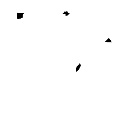
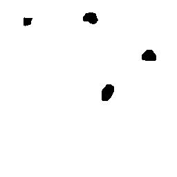
Geodesic erosion with a disc of size 1 applied 4 times.
pgeodesicerosion 2 1 4 tangrammarkers2.pan fillholbin.pan out.pan
Geodesic erosion with a disc of size 1 applied 30 times.
pgeodesicerosion 2 1 30 tangrammarkers2.pan fillholebin.pan out.pan
 |
|
 |
 |
| Binary image. | Mask image. | Geodesic erosion by a disc applied 4 times. | Geodesic erosion by a disc applied 30 times. |
The reconstruction by dilation is similar to the geodesic dilation applied until idempotence (ie., until the resulting image at the iteration i+1 equals the resulting image at iteration i). However, the mask image does not act as a mask but to force the dilation to remain above the mask image. Thus, the mask image must be greater than or equal to the marker image. With reconstruction by dilation, the structuring element is no longer a parameter of the reconstruction. Only the connectivity (4 or 8 in 2D) is used.
Rgδ(f(x,y))= δg∞(f(x,y))
Reconstruction by dilation.
pdilatationreconstruction 8 tangrammarkers1.pan fillholbin.pan brd1.pan
Geodesic dilation until idempotence with a disc of size 3x3.
pgeodesicdilatation 2 1 -1 tangrammarkers1.pan fillholebin.pan brd2.pan
|
|
 |
 |
| Binary image. | Mask image. | Reconstruction by dilation with a disc applied 4 times. | Geodesic dilation by a disc applied until idempotence. |
The reconstruction by erosion is similar to the geodesic erosion applied until idempotence (ie., until the resulting image at the iteration i+1 equals the resulting image at iteration i). However, the mask image is used in the reconstruction does not act as a mask but to force the erosion to remain below the mask image. Thus, the mask image must be lower than or equal to the marker image. With reconstruction by erosion, the structuring element is no longer a parameter of the reconstruction. Only the connectivity (4 or 8 in 2D) is used.
Rgε(f(x,y))= εg∞(f(x,y))
Reconstruction by erosion.
perosionreconstruction 8 tangrammarkers1.pan fillholbin2.pan brd1.pan
Geodesic erosion until idempotence with a disc of size 3x3.
pgeodesicerosion 2 1 -1 tangrammarkers1.pan fillholebin.pan brd2.pan
|
 |
 |
 |
| Binary image. | Mask image. | Reconstruction by erosion with a disc applied 4 times. | Geodesic erosion by a disc applied until idempotence. |
An opening is an erosion followed by a dilation. Erosion opens dark holes and dilation recovers the shape.
γB(f) = δB(εB(f)) (i.e., opening(f(x,y)) = dilation(erosion(f(x,y))))
Opening with a disc of size 7:
perosion 2 3 images/tangrambin.pan i1.pan
pdilatation 2 3 i1.pan tangram_opening.pan
|
 |
| Binary image. | Opening with a disc of size 7. |
|
 |
| Grayscale image. | Opening with a disc of size 7. |
|
 |
| Color image. | Opening with a disc of size 7. |
A closing is a dilation followed by an erosion. Dilation closes dark holes and erosion recovers the shape.
ΦB(f)) = εB(δB(f)) (i.e., closing(f) = erosion(dilation(f)))
Closing with a disc of size 19:
pdilatation 2 3 images/tangrambin.pan i1.pan
perosion 2 3 i1.pan tangramclo.pan
|
 |
| Binary image. | Closing with a disc of size 7. |
|
 |
| Grayscale image. | Closing with a disc of size 7. |
|
 |
| Color image. | Closing with a disc of size 7. |
In the opening operation, the dilation is replaced by a reconstruction by dilatation in order to recover the initial shape of the eroded objects.
γR(f) = δR(ε(f),f) (i.e., opening(f(x,y)) = dilationReconstruction(erosion(f(x,y)), f(x,y)))
Opening with a disc of size 19:
perosion 2 9 images/tangrambin.pan i1.pan
pdilatationreconstruction 8 i1.pan tangrambin.pan tangram_opening.pan
|
 |
| Binary image. | Opening by reconstruction with a disc of size 23. |
|
 |
| Grayscale image. | Opening by recontruction with a disc of size 23. |
|
 |
| Color image. | Opening by reconstruction with a disc of size 15. |
In the closing operation, the erosion is replaced by a reconstruction by erosion in order to recover the initial shape of the dilated objects.
ΦR(f) = εR(δ(f),f) (i.e., closing(f) = erosion(dilation(f)),f)
Closing with a square of size 15:
pdilatation 1 7 images/tangrambin.pan i1.pan
perosionreconstruction 8 i1.pan tangrambin.pan tangramclo.pan
|
 |
| Binary image. | Closing with a disc of size 15. |
|
 |
| Grayscale image. | Closing with a disc of size 15. |
|
 |
| Color image. | Closing with a disc of size 15. |
The geodesic reconstruction by dilation is the same operation as the reconstruction by dilatation, except that the operation has an additional parameter that can control the number of dilation. If this parameter is set to -1, the operation is the same as the reconstruction by dilatation.
The geodesic reconstruction by erosion is the same operation as the reconstruction by erosion, except that the operation has an additional parameter that can control the number of erosion. If this parameter is set to -1, the operation is the same as the reconstruction by erosion.
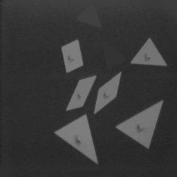
Area opening removes all white connected components whose area in number of pixels is smaller than a given threshold value. With this operation only the size information is taken into consideration; there is no restriction on the shape.
The algorithm presented in a naive way consists in:
It can be extended to grayscale images to remove all bright structures that have less than the specified number of pixels.
Area opening to remove tangram pieces smaller than 500 pixels:
pareaopening 8 50 images/tangrambin.pan tangramao1.pan
|
 |
| Binary image. | Area opening of size 500 pixels. |
|
 |
| Grayscale image. | Area opening of size 800 pixels. |
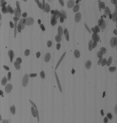
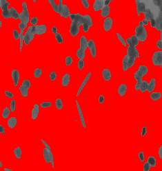
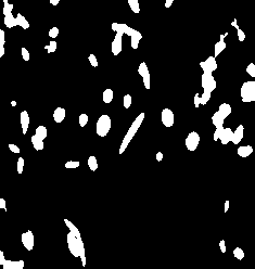
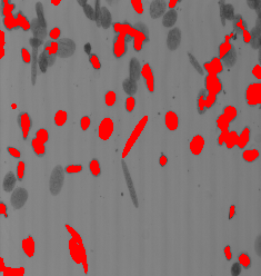
Area closing removes all dark connected components whose area in number of pixels is smaller than a given threshold value. With this operation, only the size information is taken into consideration; there is no restriction on the shape.
The algorithm presented in a naive way consists in:
It can be extended to grayscale images to remove all dark structures that have less than threshold pixels.
Area closing to remove black dots smaller than 20 pixels:
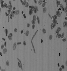
pareaclosing 8 20 images/esophagusbin.pan esophagusac1.pan
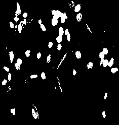
Area closing with an area of 500 to remove cells smaller than 500 pixels:
pareaclosing 8 500 images/esophagusgray.pan esophagusac2.pan
 |
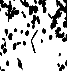 |
| Binary image. | Area closing of size 20 pixels. |
 |
 |
| Grayscale image. | Area closing of size 500 pixels. |
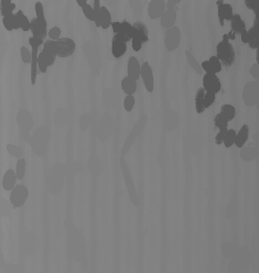
These operations are used to detect in a binary or grayscale image peaks or troughs of a certain size independently from their hight.
Morphological top-hats proceeds a contrario. The approach undertaken with top-hats consists of using knowledge about the shape characteristics that are not shared by their relevant image structures. It is sometimes easier to remove relevant structures than trying to directly suppress irrelevant objects. The size and shape of the structuring element used for morphological top-hat depends on the morphology of the structures to be extracted. e.g., to detect bright features of width smaller than w, a WTH with a disc structuring element slightly larger than w should be considered.
If the image is corrupted by a high-frequency noise, it must be filtered before using the morphological top-hat: a closing by a small structuring element before calculating a WTH and an opening before a BTH.
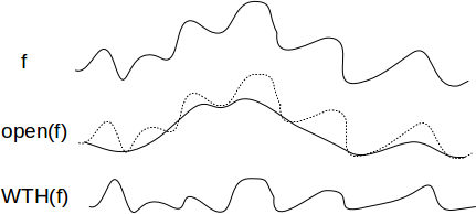
White top-hat is the difference between the original image and its opening:
WTH(f) = f-γ(f)
If the image is corrupted by noise, a closing by small structuring element should be applied first.
perosion 1 8 images/tangram.pan i1.pan
pdilatation 1 8 i1.pan i2.pan
psub tangram.pan i2.pan wth.pan
|
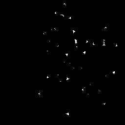 |
| Binary image. | WTH with a disc of size 7. |
|
 |
| Gray image. | WTH with a disc of size 7. |
|
 |
| Color image. | WTH with a disc of size 7. |
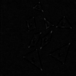
Black top-hat is the difference between the closing of an image and the image itself:
BTH(f) = Φ(f)-f
If the image is corrupted by noise, an opening by small structuring element should be applied first.
pdilatation 1 8 images/tangram.pan i1.pan
perosion 1 8 i1.pan i2.pan
psub i2.pan tangram.pan bth.pan
|
 |
| Binary image. | BTH with a disc of size 7. |
|
 |
| Gray image. | BTH with a disc of size 7. |
|
 |
| Color image. | BTH with a disc of size 7. |
The sum of the black top-hat and white top-hats extracts both peaks and troughs.
SCTH(f) = WTH(f)+BTH(f)
perosion 2 2 images/tangramgray.pan i1.pan
pdilatation 2 2 i1.pan i2.pan
psub images/tangramgray.pan i2.pan wth.pan

pdilatation 2 2 images/tangramgray.pan i1.pan
perosion 2 2 i1.pan i2.pan
psub i2.pan images/tangramgray.pan bth.pan

padd wth.pan wth.pan self.pan
|
|
|
 |
| Binary image. | White Top-Hat. | Black Top-Hat. | Self-Complementary Top-Hat. |
The closing is replaced by a closing by reconstruction.
perosion 1 8 images/tangram.pan i1.pan
pdilatationreconstruction 8 i1.pan images/tangram.pan i2.pan
pdif images/tangram.pan i2.pan gwth.pan
The opening is replaced by an opening by reconstruction.
pdilatation 1 8 images/tangram.pan i1.pan
perosionreconstruction 8 i1.pan images/tangram.pan i2.pan
pdif images/tangram.pan i2.pan gbth.pan
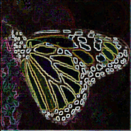
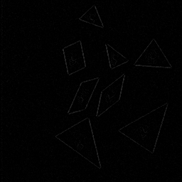
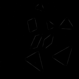
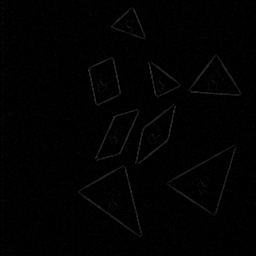
The gradient is used in image processing to detect edges. A common assumption is that object edges are located where there are high grayscale variation. The gradient returns the maximum variation of the grayscale intensities within the neighborhood defined by the structuring element.
The morphological gradient is defined as the difference between a dilation and an erosion by the structuring element B:
ρB(f)=δB(f)-εB(f) = dilation(f)-erosion(f)
The dilation is responsible for the external gradient and the erosion is responsible for the internal gradient. It is equivalent to the norm of the gradient : ||∇f||.
pdilatation 1 1 images/tangramgray.pan i1.pan
perosion 1 1 images/tangramgray.pan i2.pan
pdif i1.pan i2.pan grad.pan
|
: |  |
- |  |
= |  |
| Grayscale image. | Dilation. | Erosion. | Gradient image. | |||
|
: |  |
- |  |
= |  |
| Color image. | Dilation. | Erosion image. | Gradient image. |
The thickness of a step-edge detected by a morphological gradient ρ(f) equals two pixels, one pixel on each side of the edge. A zero-thickness can be achieved with inter-pixel approaches, or by defining the edge as the interface between two adjacent regions. Half-gradients can be used to detect either the internal or the external boundary of an edge.
The internal gradient enhances the internal boundaries of objects brighter than their background and external boundaries of objects darker than their background.
ρ-B(f)=f-εB(f)
The external gradient enhances the internal boundaries of objects darker than their background and external boundaries of objects brighter than their background.
ρ+B(f)=δB(f)-f
Internal gradient:
perosion 1 1 images/tangramgray.pan i1.pan
pdif images/tangramgray.pan i1.pan internal.pan
External gradient
pdilatation 1 1 images/tangramgray.pan i2.pan
pdif images/tangramgray.pan i2.pan external.pan
|
- |  |
= |  |
| Binary image. | Erosion. | Internal gradient (ρ-). | ||
|
- |  |
= |  |
| Dilation. | Binary image. | External gradient (ρ+). |
Directional gradient is defined by using linear structural element. It outputs the highest values for the linear structures on the image that have the same direction than the structuring element:
ρL(f) = δL(f)-εL(f)
plineardilation 0 0 1 images/tangramgray.pan i1.pan
plinearerosion 0 0 1 images/tangramgray.pan i2.pan
pdif i1.pan i2.pan grad.pan
|
: |  |
- |  |
= |  |
| Grayscale image. | Horizontal dilation. | Horizontal erosion. | Horizontal gradient. |
If the size of the structuring element is greater than 1, the morphological gradient is referred as thick gradient. Thick gradient are suitable when the transitions between objects are smooth.
pdilation 1 5 images/tangramgray.pan i1.pan
perosion 1 5 images/tangramgray.pan i2.pan
pdif i1.pan i2.pan grad.pan
|
: |  |
- |  |
= |  |
| Grayscale image. | Dilation of size 11. | Erosion of size 11. | Resulted gradient image. |
The multiscale gradient avoids the problems of the thick gradient that yields thick edges and merges two edges that are at a distance lower than the structuring element size.
The thickness of the gradient of size n can be reduced by using an erosion of size n-1. The separation of two edges can be done by using a white top-hat. As a result, the multiscale gradient is:
ρ*nB= ε(n-1)B(WTHnB(ρnB))
It is then possible to compute an edge map with various scales and structuring elements as the union of the various multiscale gradients:
ρ* = ⋃nB(ρ*nB)
psetsct 0 in.pan out.pan

n=$tmin;
while [ $n -le thmax ]; do
  # Thick gradient
  pdilation $se $n in.pan i1.pan
  perosion $se $n in.pan i2.pan
  pdif i1.pan i2.pan i3.pan

  # White top-hat
  perosion $se $n i3.pan i4.pan
  pdilation $se $n i4.pan i5.pan
  pdif i5.pan i3.pan i6.pan

  # Thichness reduction
  np=`expr $n - 1`
  if [ $np -ge 1 ]
  then
    perosion $se $np i6.pan i6.pan
  fi

  # Union of the gradients
  pmax i6.pan out.pan out.pan
  n=`expr $n + 1`
done
|
: |  |
⋃..⋃ |  |
= |  |
| Grayscale image. | Gradient of size 3. | Gradient of size 11. | Resulted multiscale gradient. |
The morphological Laplacian is defined as the arithmetic difference between the internal and the external gradient. The object boundaries are located at the zero-crossing of the Laplacian image.
pdilation se hs in.pan i1.pan
psub i1.pan in.pan c.pan

perosion se hs in.pan b.pan
psub in.pan b.pan d.pan

psub c.pan d.pan out.pan
H-maxima transformation suppresses any domes with height smaller or equal than a threshold level h and decreases the height of the other domes by h. It is defined as the reconstruction by dilation of f subtracted by a height h.
HMAXh(f) = Rδf(f-h)
paddcst -30 images/esophagusgray.pan tmp.pan
pdilationreconstruction 8 tmp.pan images/esophagusgray.pan hmaxima.pan
|
 |
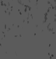 |
| Input image. | H-maxima of height 30. | H-maxima of height 50. |
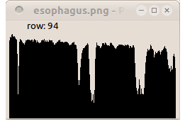 |
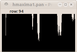 |
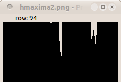 |
| Profile of line 94. | Profile of line 94. | Profile of line 94. |
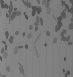
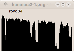
H-minima transformation removes any trough with depth smaller or equal than h and increases the height of the other troughs by h. It is defined as the reconstruction by erosion of f increased by a height h.
HMINh(f) = Rεf(f+h)
paddcst 30 images/esophagusgray.pan tmp.pan
perosionreconstruction 8 tmp.pan images/esophagusgray.pan hminima.pan
|
 |
 |
| Input image. | H-minima of height 30. | H-minima of height 50. |
 |
 |
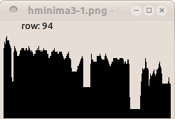 |
| Profile of line 94. | Profile of line 94. | Profile of line 94. |
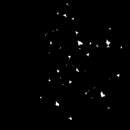
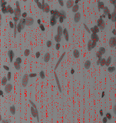
The regional maxima are all pixels that are higher than any pixel in its neighborhood. They can be computed from the residue of the h-maxima of height 1.
RMAX(f) = f - HMAX1(f)
# smoothing
pmeanfiltering 1 images/esophagusgray.pan in.pan

# RMAX
paddcst -1 in.pan tmp1.pan
pdilationreconstruction 8 tmp1.pan in.pan tmp2.pan
pdif in.pan tmp2.pan tmp3.pan
pbinarization 1 1 tmp3.pan out.pan
|
 |
 |
| Input image f. | RMAX(f). | Localization of the markers. |
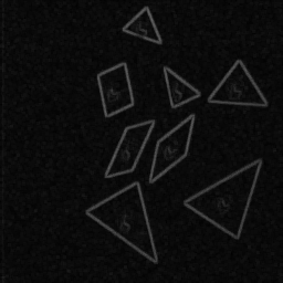
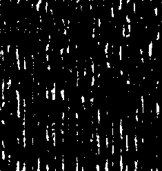
The regional minima are all pixels that are lower than any pixel in its neighborhood. They can be computed from the residue of the h-minima of height 1.
RMIN(f) = HMIN1(f) - f
# smoothing
pmeanfiltering 1 images/esophagusgray.pan in.pan

# RMIN
paddcst +1 in.pan tmp1.pan
perosionreconstruction 8 tmp1.pan in.pan tmp2.pan
pdif tmp2.pan in.pan tmp3.pan
pbinarization 1 1 tmp3.pan out.pan
|
 |
 |
| Input image f. | RMIN(f). | Localization of the markers. |
The extended maxima EMAX are defined as the regional maxima of the corresponding h-maxima transformation:
EMAXh(f) = RMAX( HMAXh(f) )
# smoothing
pmeanfiltering 1 images/esophagusgray.pan in.pan

# HMAX with h=30
paddcst -30 in.pan tmp.pan
pdilationreconstruction 8 tmp.pan in.pan hmaxima.pan

# RMAX (HMAX)
paddcst -1 hmaxima.pan tmp1.pan
pdilationreconstruction 8 tmp1.pan hmaxima.pan tmp2.pan
pdif hmaxima.pan tmp2.pan tmp3.pan
pbinarization 1 1 tmp3.pan emax.pan
|
 |
 |
| Input image f. | EMAX(f). | Localization of the markers. |
The extended minima EMIN are defined as the regional minima of the corresponding h-minima transformation:
EMINh(f) = RMIN( HMINh(f) )
# smoothing
pmeanfiltering 1 images/esophagusgray.pan in.pan

# HMIN with h=30
paddcst 30 in.pan tmp.pan
perosionreconstruction 8 tmp.pan in.pan hminima.pan

# RMIN (HMIN)
paddcst +1 hminima.pan tmp1.pan
perosionreconstruction 8 tmp1.pan hminima.pan tmp2.pan
pdif tmp2.pan hminima.pan tmp3.pan
pbinarization 1 1 tmp3.pan emin.pan
|
 |
 |
| Input image f. | EMIN(f). | Localization of the markers. |
The average of the erosion and the dilation of an image is analogous to image smoothing.
DYT(f)=1/2[erosion(f)+dilation(f)]
pdilation 1 1 images/tangramgray.pan tmp1.pan
perosion 1 1 images/tangramgray.pan tmp2.pan
pmean tmp1.pan tmp2.pan dyt.pan
|
= |  |
| f. | DYT(f). |
The average of the opening and the closing of an image is analogous to image smoothing which mimics the response to the median filter.
TET(f)=1/2[opening(f)+closing(f)]
pdilation 1 1 images/tangramgray.pan tmp1.pan
perosion 1 1 tmp1.pan tmp2.pan

perosion 1 1 images/tangramgray.pan tmp3.pan
pdilation 1 1 tmp3.pan tmp4.pan

pmean tmp3.pan tmp4.pan tet.pan
|
= |  |
| f. | TET(f). |
Filtering an image containing dark and bright noise can be achieved by a sequence of close-open filters:
A solution to is to alternate closings and openings beginning with a small structuring element and then proceeding with the ever-increasing structuring element until a given size is reached.
ASFrec(closing_n(Opening_n(closingn_1(opening_n-1(closingn_2(... (closing1(opening_1(f)))))))) where n is the size of the filter.
cp in.pan out.pan
i=1
while [ $i -le $n ]
do
#geodesic opening
perosion $se $i out.pan i1.pan
pdilationreconstruction 8 i1.pan out.pan i2.pan

#geodesic closing
pdilation $se $i i2.pan i3.pan
pdilationreconstruction 8 i3.pan i2.pan out.pan
i=`expr $i + 1`
done
A simple neighborhood-based morphological contrast operator by adding the white top-hat to the original image to enhance bright objects, and subtracting the black top-hat from the resulting image to enhance dark objects. All the pixels falling outside the dynamic range of the original image [ymin, tmax] are clipped.
Κth = f + WTH(f) - BTH(f) = f + f - γB - ΦB + f = 3.f - γB - ΦB
perosion 2 2 esophagusgray.pan i1.pan
pdilation 2 2 i1.pan i2.pan
psub esophagusgray.pan i2.pan wth.pan

pdilation 2 2 esophagusgray.pan i3.pan
perosion 2 2 i3.pan i4.pan
psub i4.pan esophagusgray.pan bth.pan

pim2sl esophagusgray.pan i5.pan
padd i5.pan wth.pan i6.pan
psub i6.pan bth.pan enhanced.pan
The major enhancement can be observed inside the cells.
 |
 |
 |
 |
| Input image f. | White Top-Hat (inversed). | Black Top-Hat (inversed). | Output image: f+WTH(f)-BTH(f). |
Distinguishing smooth "ramp" edges from ripple "texture edges" i.e: non ramp edges are texture or noise:
GT(f) = ω(f) - ε(f)
GR = ρ(f) - GT(f)
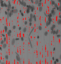
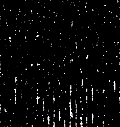
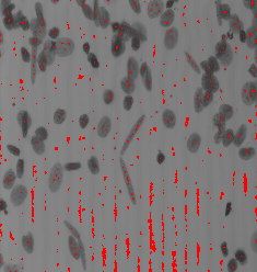
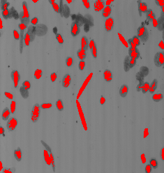
Marker extraction is one the crucial step in watershed segmentation. A marker is a region that must be placed inside an object to be extracted.
The markers are all pixels that are lower (or higher) than any pixel in their neighborhood. This is direct application of the operation RMIN (or RMAX).
paddcst 1 images/esophagusgray.pan tmp1.pan
perosionreconstruction 8 tmp1.pan images/esophagusgray.pan tmp2.pan
pdif tmp2.pan images/esophagusgray.pan tmp3.pan
pbinarization 1 1 tmp3.pan out.pan
The regional extrema operation (RMIN) is preceded by a closing by a disk of radius 3 in order to reduce the number of regional minima.
pdilation 2 3 images/esophagusgray.pan tmp1.pan
perosion 2 3 tmp1.pan tmp2.pan

paddcst 1 tmp2.pan tmp3.pan
perosionreconstruction 8 tmp3.pan tmp2.pan tmp4.pan
pdif tmp4.pan tmp2.pan tmp5.pan
pbinarization 1 1 tmp5.pan out.pan
The regional extrema operation (RMIN) is preceded by a reconstruction from opening by a disk of radius 3.
pdilation 2 3 images/esophagusgray.pan tmp1.pan
perosionreconstruction 8 tmp1.pan images/esophagusgray.pan tmp2.pan

paddcst 1 tmp2.pan tmp3.pan
perosionreconstruction 8 tmp3.pan tmp2.pan tmp4.pan
pdif tmp4.pan tmp2.pan tmp5.pan
pbinarization 1 1 tmp5.pan out.pan
The regional extrema operation (RMIN) is preceeded by an area opening by a disk of radius 3.
pareaclosing _ 100
paddcst 1 tmp2.pan tmp3.pan
perosionreconstruction 8 tmp3.pan tmp2.pan tmp4.pan
pdif tmp4.pan tmp2.pan tmp5.pan
pbinarization 1 1 tmp5.pan out.pan
The regional extrema operation (RMIN) is preceeded by a H-minima detection.
paddcst 1 tmp2.pan tmp3.pan
perosionreconstruction 8 tmp3.pan tmp2.pan tmp4.pan
pdif tmp4.pan tmp2.pan tmp5.pan
pbinarization 1 1 tmp5.pan out.pan
|
 |
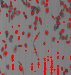 |
| Input image. | Regional minima. | Regional minima of closing by a disk of radius 3. |
 |
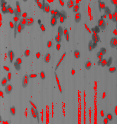 |
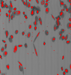 |
| Regional minima of reconstructive closing by a disk of radius 3. | Regional minima of area closing (size = 50). | Regional minima of H-Minima (h=10). |
To force the watershed to pass into certain points or lines, they must be introduced as maxima in the source image.
pbinarization 0 0 germes.pan i1.pan
padcst 1 in.pan i2.pan
pmin i1.pan i2.pan i3.pan
perosionreconstruction 8 i1.an i3.pan swamping.pan
Generalized Voronoï diagram: create an image by detection of the lines that are equidistant between two or more connected components.
pbinarization 100 1e30 images/tangramgray.pan i1.pan
pdistance i1.pan i2.pan
plabeling 8 i1.pan i3.pan
pwatershed i3.pan i2.pan i4.pan
pboundary 8 i4.pan skiz.pan
|
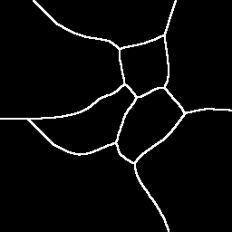 |
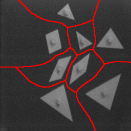 |
| A gray image. | The skiz. | Superimposition of the skiz. |
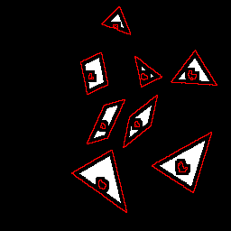
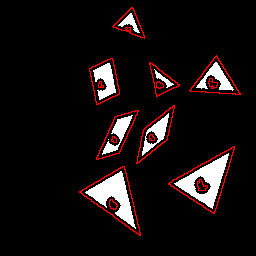
Hit or miss is used to find location of one shape among a set of shapes. The shape is defined by two structuring elements: im_se1 is a structuring element that specifies the object part, and im_se2 specified the background part. The transformation can be summarised by the question: "does im_se1 fits the object part while im_se2 fits the object background?."
[UHMT(f)](x) = [erosionse1(f)](x) - [dilationse2(f)](x); if [erosionse1(f)](x) > [dilationse2(f)](x)
               0 otherwise
Detect straight lines in the gradient image.
cat > se1.txt << EOF
255 0 3
255 1 3
255 2 3
255 3 3
255 4 3
EOF
cat > se2.txt<<EOF
255 2 0
255 2 1
255 2 5
255 2 6
EOF
ptxt2pan 0 5 7 0 se1.txt se1.pan
ptxt2pan 0 5 7 0 se2.txt se2.pan
pgradient 1 images/tangramgray.pan tmp1.pan tmp2.pan
phitormiss se1.pan se2.pan tmp1.pan tmp2.pan
pbinarization 1 1e30 tmp3.pan hitormiss.pan
|
 |
 |
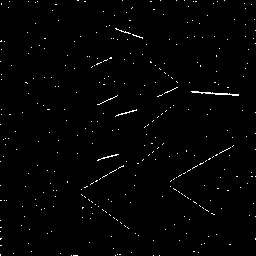 |
| A gray image. | The object structuring element (x3). | The background structuring element (x3). | Superimposition of the skiz. |
An ultimate eroded is the last connected component that remains after successive erosion of a region. The ultimate eroded set is the union of all connected components disparing at each erosion step. This is also the maxima of the distance image.
This operation produces an image where each basin of g is valued. This valuation leads to a simplified image f' made of tiles of constant gray values.
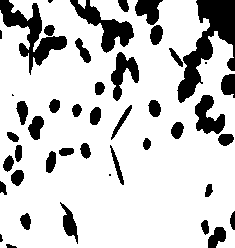
The holes in a binary image are supposed to be a set of background pixels that are not connected to the image border. Hence, filling the holes of a binary image consists in removing all background pixels which are not connected to the image border. This is done by using a reconstruction by erosion where the marker image is a white image except along its border where the values of the original image is used.
This can be extended to grayscale images. In this case, the holes are supposed to be the regional minima that are not connected to the image border.
psetcst 255 images/tangrambin.pan i1.pan
pcopyborder 1 1 1 1 1 1 images/tangrambin.pan i1.pan markers.pan
perosionreconstruction 4 markers.pan images/tangrambin.pan fillholebin.pan
|
 |
|
| A binary image. | The marker image (a white image with a black border). | The reconstruction by erosion. |
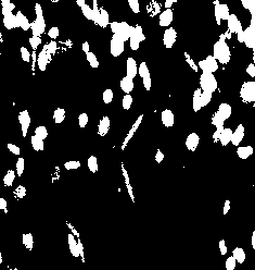
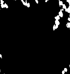
Assuming objects are sets of white pixels and background is set of black pixels, objects connected to the image border are extracted using reconstruction by dilation of the input image into a mask image equals to a black image except along its border where the value of the input image are considered. A simple subtraction with the input image removes the object connected to the image border.
The detection and removal of objects connected to the image border can be extended to grayscale images. This can be used to remove regions connected to the image border that are equals or brighter than the connected border pixels.
psetcst 0 images/tangrambin.pan i1.pan
pcopyborder 1 1 1 1 1 1 images/tangrambin.pan i1.pan markers.pan
pdilationreconstruction 8 markers.pan images/tangrambin.pan borderobjectbin1.pan
pdif images/eosophagusbin.pan borderobjectbin1.pan borderobjectbin2.pan
 |
 |
 |
| A binary image. | The reconstruction by dilation. | Result of the suppression. |
Rotational Morphological Procesing (RMP) operated
morphological operations by considering several rotations of
the image with respect to the structuring that is fixed in one direction.
It assumes that the full 180° angles are equally divided into
N directions, the function fi denotes the rotation
of the original image f by the degree θi = 180 i/N.
The image is rotated clockwise on the centre of the image frame.
The image operated by the RMP are followed by rotation at θi
degrees in the counter-clockwise direction. The processed images
are finally compiled together by combining pixel values according
+to certain rules; for exemple the max, min values of the pixel
in each rotated images.
Grayscale structuring elements can be used to perform fuzzy morphological
processing.
The structuring element Bis not only a mask, but a matrix of
the weight assigned to each pixel in the structuring element.
The idea is to rate the contribution to each point of the mask
by: value/255. During the set of operations, the value
of a pixel f(x,y) masked by the structuring element value B(i,j)
is: f(x,y)*B(i,j)/255.
This is not implemented in the current Pandore library.V.B. Fuzzy Rotational Morphological Processing
References
The Pantheon project
Image Team GREYC Laboratory
UMR CNRS 6072 - ENSICAEN - University of Caen, France
This page was last modified on
24 June 2016